HC-SR04 with CircuitPython
Learn how to use the HC-SR04 ultrasonic sensor with CircuitPython. Step-by-step tutorial with code and wiring diagram.
Jan. 2, 2026
The HC-SR04 ultrasonic sensor is one of the most popular components for measuring distance in robotics and automation projects. Its simplicity and low cost make it ideal for both beginners and advanced users. In this tutorial, we will explore how to integrate it efficiently using CircuitPython, testing the project on a Raspberry Pi Pico.
The advantage of using CircuitPython here is the readability of the code and the vast amount of ready-to-use libraries, such as Adafruit's, which abstracts all the complexity of the trigger and echo pulses.
Necessary Materials
To follow this tutorial, you will need the following components:
- Development Board: Raspberry Pi Pico (or any other CircuitPython-compatible board).
- Ultrasonic Sensor: HC-SR04 (Standard 5V version) or the modern HC-SR04P / HC-SR04+ versions (which operate at 3.3V).
- Logic Level Converter: Mandatory only if you are using the standard 5V sensor with the Raspberry Pi Pico.
- Jumper Wires: 10 units (if using a logic converter) or 4 units (direct connection).
- Breadboard: 400 points (and an auxiliary 170-point breadboard if using the converter).
- Software:
circup(for libraries) andmpremote(for execution).
HC-SR04 Versions: 3.3V vs 5V
Before connecting the wires, it is crucial to identify which version of the sensor you have.
- HC-SR04 (Old Standard): Operates strictly at 5V. Since the Raspberry Pi Pico (and most modern boards) works with 3.3V on the GPIO pins, you cannot connect the sensor's "Echo" pin directly to the board, as the 5V return signal can burn out the microcontroller's port. In this case, it is necessary to use a logic level converter or a voltage divider.
- HC-SR04P or HC-SR04+: These are updated versions that operate over a wider voltage range (usually 3V to 5.5V). If you have one of these, you can connect it directly to the Raspberry Pi Pico's 3.3V pins without additional components.
Wiring Diagram and Pinout
Below, we describe the pinout for both scenarios.
Scenario A: HC-SR04P / HC-SR04+ (3.3V)
If your sensor is 3.3V compatible, the connection is direct:
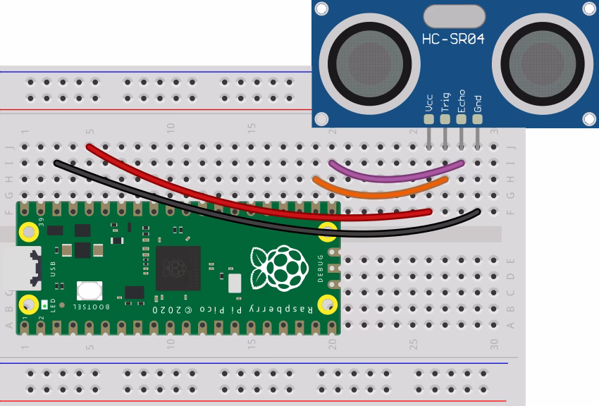
- VCC: Connect to the 3V3 (OUT) pin on the Pico.
- GND: Connect to any GND on the Pico.
- Trig: Connect to GP17.
- Echo: Connect to GP16.
Scenario B: Standard HC-SR04 (5V) with Level Converter
If your sensor is the classic 5V model, you must power the sensor with 5V (VBUS), but convert the communication signals to 3.3V:
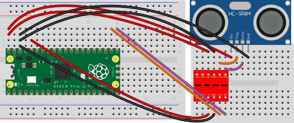
- Sensor Power: VCC to VBUS (5V) on the Pico and GND to GND.
- Logic Converter (HV Side - High Voltage): Connect to 5V (VBUS).
- Logic Converter (LV Side - Low Voltage): Connect to 3V3 (OUT).
- Signals (via Converter):
- Trig: Pico GP17 -> LV3 -> HV3 -> Sensor Trig.
- Echo: Sensor Echo -> HV4 -> LV4 -> Pico GP16.
Environment Setup
We will use two essential tools from the Python ecosystem for microcontrollers: circup to manage packages and mpremote to control the board.
Installing the Library
CircuitPython has an official Adafruit library specifically for this sensor, which makes the work much easier. Connect your board via USB and run the following in your terminal:
circup install adafruit_hcsr04The command above will download the adafruit_hcsr04.mpy driver and automatically copy it to the lib folder on your board.
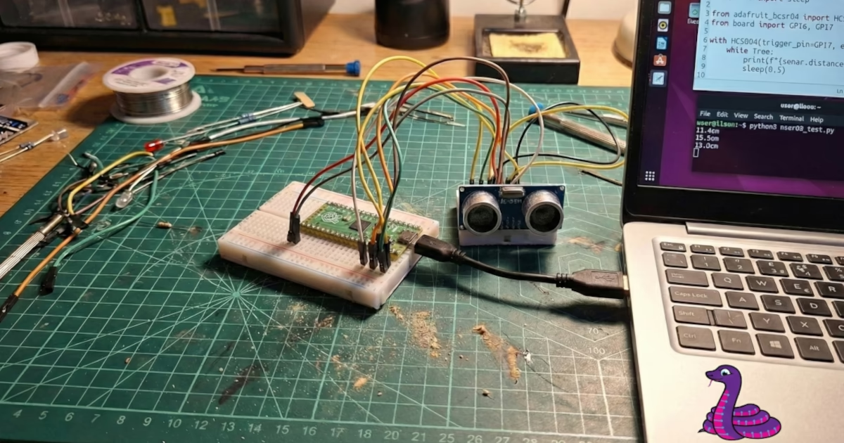
The Code
Copy the code below and save it as main.py (or another name of your preference) on your computer.
from time import sleep

from adafruit_hcsr04 import HCSR04
from board import GP16, GP17

with HCSR04(trigger_pin=GP17, echo_pin=GP16) as sonar:
    while True:
        print(f"{sonar.distance:.1f}cm")
        sleep(0.5)
Understanding the Script
- Imports: We import the
HCSR04class from the library we installed and define pinsGP16andGP17via theboardmodule. - Context Manager (
with): We use thewithstatement to initialize the sensor. This is a best practice in CircuitPython as it ensures hardware resources (the pins used) are correctly released if the code is interrupted or finished, preventing "pin in use" errors when restarting the script. - .distance Property: The reading is done by accessing
sonar.distance. The library automatically calculates the sound's time of flight and returns the value already converted to centimeters (float). - Loop: The code reads the distance and prints it to the console every 0.5 seconds.
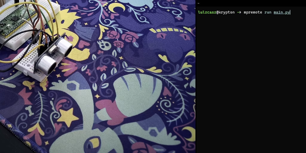
Running the Project
With the code saved and the board connected, use mpremote to run the script directly:
mpremote run main.pyYou should see distance measurements updating in real-time in your terminal.
Conclusion
Using the HC-SR04 with CircuitPython is extremely straightforward thanks to the abstraction provided by the Adafruit library. Always remember to check your sensor's operating voltage to protect your Raspberry Pi Pico.